The CY-822B USB led-joystick controller board
I wanted to build myself a MAME pedestal with a Raspberry Pi 3. I ordered a cheap joystick plus LED kit from eBay, and it came with this controller board. The print on the back reads USB CY-822B led-joystick. After a lot of Google searches, I came up pretty empty on results. So I decided I would post what I know about this board for others.
Below, you can see what the back side label says, and what the MAME software reads it as. Example, the top plug is K1 according to the back of the board (see the back side of the board picture below). The MAME software reads the button plugged in as L2.
 |
| USB CY-822B led-joystick controller board |
 |
| USB CY-822B led-joystick controller board - back side |
I read another post somewhere referring to this board as the Bosega 822. Is it made by Bosega? I have no clue.
 |
| Bosega USB CY-822B led-joystick schematic |
Many eBay listers just copy bad information from other sites for their listings, and don't provide any useful information for noobs like me in setting this up.
MODE - this port is absolutely useless. Might as well fill it in with hot glue. What does it do? It switches the Joystick input from the digital d-pad to the analogue joystick. Thing is, this board doesn't have the analogue joystick socket. It may be possible to solder on some sort of connection for an analogue joystick, but that will have to be for another post.
TURBO - this button is used by pressing it PLUS any other of the switch buttons. Let's say I want to put the L1/A button into auto fire. It press AUTO and L1/A at the same time. L1/A is now in auto fire mode. Instead of having to tap tap tap constantly on L1/A, I can just hold it down, and the controller will tap tap tap for me.
CLR - this clears the button. If L1/A is in AUTO mode, I press CLR + L1/A to set it back to normal mode.
AUTO - use it in the same way as TURBO. The difference is the controller will tap tap tap the button without me having to press the button.
This board is designed to pass USB 5V to an LED button. Depending on how the connector cable is configured, the LED in the button will either always be on, or only illuminate when pressed. I found this reference image.
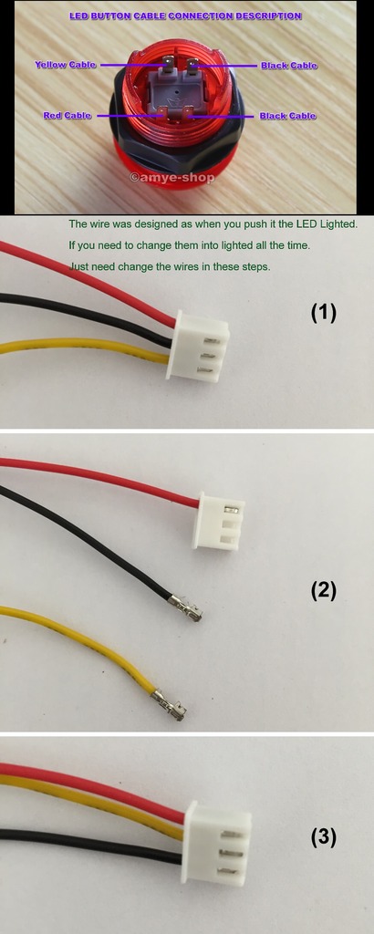
When connected to the controller board

Outer Pin (OP), Centre Pin (CP), Inner Pin (IP).
OP is COMMON or GROUND. IP and CP read at 5V. Pressing the button closes the connection between OP and CP, grounding CP. Depending on how the button is wired, the LED on IP is either grounded always (always on), or the LED needs the button to be pressed to complete the circuit (illuminate on press).
My wires came configured as always on. I like the way my MAME console looks with all the buttons lit up. I'll have to check what the current draw is with all the LEDs lit. Since I have two controllers, that's 24 LEDs drawing 5V from the USB power supply connected to my Raspberry Pi 3. It didn't seem to have any issues. I plan on using a powered USB hub between the RPi3 and controllers anyway.